3.4 Working with paths
3.4.1 Path following
Animating an object by moving it along a path is simple to implement. Changing the orientation of the object has to be taken into consideration. The path must be smoothed before it can be used. If the path is constrained to lie on the surface of another object, the more computation is involved.
3.4.2 Orientation along a path
Typically, a local coordinate system(u,v,w) is defined for an object to be animated. A right-handed coordinate system is assumed, with the origin of the coordinate system determined by a point along the path P(s). This point is generated based on the frame number, arc length parameterization, and possibly ease-in/ease-out control. This position will be referred to as POS. The direction the object is faicing is identified with the w-axis, the upvector is identified with the v-axis, and the local u-axis is perpendicular to these two.
There are various ways to handle the orientation of the camera. The orientation is specified by determining the direction it is pointing(the w-axis) and the direction of its up vector(the v-axis); the u-axis is then fully specified by completing the left-handed camera coordinate system(eye space).
Use of the Frenet frame
If an object is following a path, then its orientation can be made dependent on the properties of the curve. The Frenet frame can be defined along the curve as a moving coordinate system (u, v, w), determined by the curve's tangent and curvature. The Frenet frame changes orientation over the length of the curve. It is defined as normalized orthogonal vectors with w in the direction of the first derivative(P'(s)), v orthogonal to w and in general direction of the second derivative P''(s) and u formed to complete. For example, a left-handed coordinate system as computed in right-handed space. At a given parameter value s, the left-handed Frenet frame is calculated.

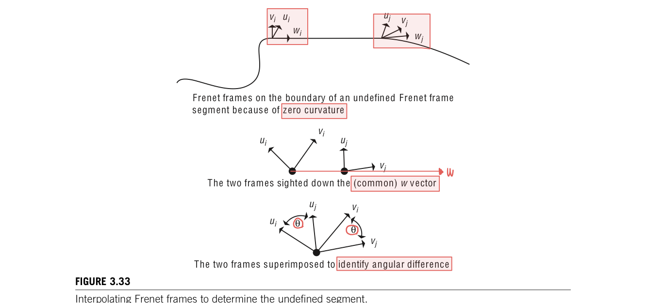
There are few problems with using it directly to control the orientation of a camera. First, there is no concept of "up" in the formation of the Frenet frame. The v vector merely lines up with the direction of the second derivative. Another problem occurs in segments of the curve that have no curvature(P''(u)=0) because the Frenet frame is undefined. These undefined segments can be dealt with by interpolating a Frenet frame along the segment from he Frenet frames at the boundary of the segment. There is no curvature along this segment, so the boundary Frenet frames must differ by only a rotation around w. The angular difference between the two can be determined by taking the arccosine of the dot product between the two vectors so that theta = acos(v1 dot v2). This rotation can be linearly interpolated along the no-curvature segment
The problem is that there is a discontinuity in the curvature vector as is common with piecewise cubic curves. For example, considera curve composedof two semicircular segments. The curvature vector which foranypoint along this curve will point to the ceneter of the semi circle will instantanenously switch from pointing one center point to the pointing the other center point at the junction of the two semicircular segments. The Frenet frame is defined everywhere but has a discontinous jump in orientation at the junction.

However, the main problem with using the Frenet frame as the local coordinate frame is that the resulting motions are usually too extreme and not natural looking(maybe because of the discontinuity). Using the w-axis(tangent vector) as the view direction of a camera can be undesirable. (Because) Often, the tangent vector does not appearto correspond to the direction of "where it is going". For example, for some one riding a bike, would be to look farther ahead along the curve rather than look tangential to the current location.
In addition, if the v-axis is equated with the up vector of an object, the object will rotate wildly. The problem becomes more obvious as the path bends up and down in space; the camera will flip between being upright and traveling along the path upside down. Frenet frame's direct use to control object orientation is clearly of limited value.
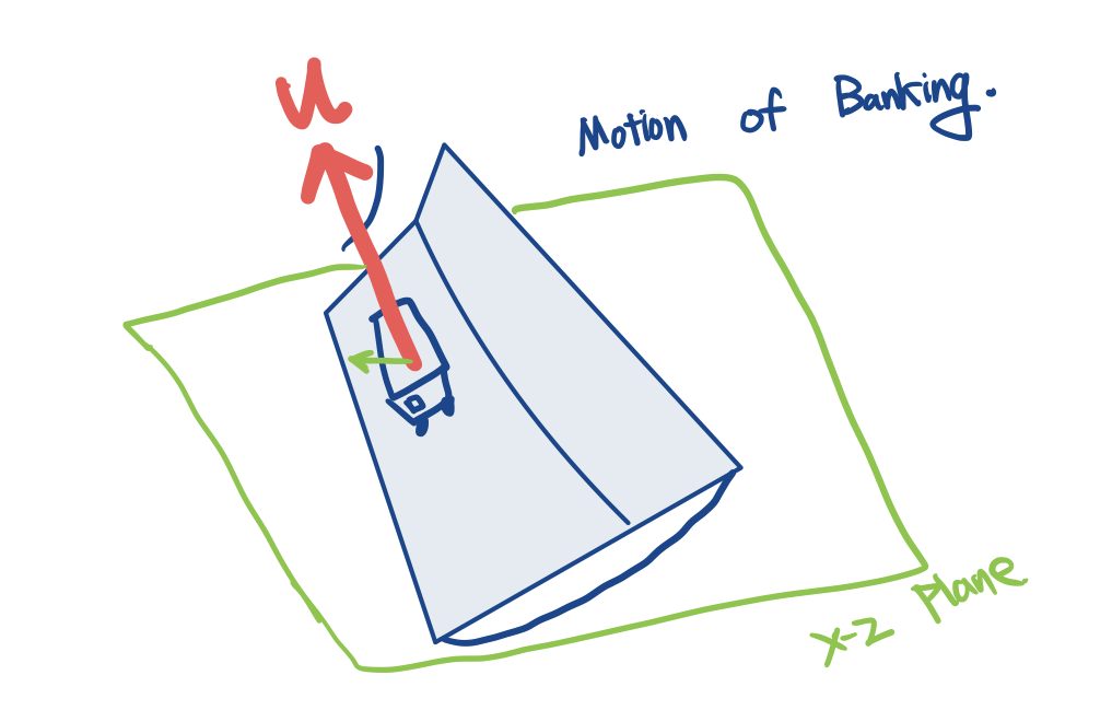
hen modling the motion of banking into a turn, the curvature vector (u-axis) does indiciate which way to bank and can be used to control the magnitude of the bank. For example, the horizontal component(in the x-z plane) of the u-axis can be used as the direction/magnitude indicator for the bank. Animator may want the object to tilt away from the curvature vector to give the impression of the object feeling a force that throws it off the path, such as a person ridinga roller coaster

Camera path following
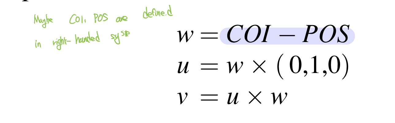
The method of specifying the orientation of a camera is to set its center of interest to a fixed point or to use the center of point of one of the objects. COI is available for calculating the view vector, w= COI - POS. This is usually a good method when the path is one that circles some arena of action.
This still leaves one degree of freedom to be determined. Assume that the up vector, v, is to be kept "up". 'Up' in this case means "generally in the positive y-axis direction." The v-axis is at right angles to the view vector(w-axis). The local coordinate system can be computed as shown in Equation 3.3 for a left-handed camera coordinate-system computed in right-handed space
The view direction can be automatically set in several ways. The COI can be set to a specific point. This works well as long as there is a single point or object on which the camera should focus and the camera does not pass too close to the point or object. Passing close to the COI will result in radical changes in view direction. Other method use points along the path itself, a separate path through the environment or interpolation. The up vector can also be set in several ways. The default orientation is fsor the up vector to lie in the plane of the view vector and the global y-axis. Alternatively, a tilt of the up vector can be specified away from the default orientation as a user-specified value. And, finally, the up vector can be specified by the user.
the simplest method of setting the view vector is to use a delta parametric value to define the COI. If the position of the camera on a curve is defined by P(s), then the COI will be P(s+delta s). This should be after reparameterization by arc length. Otherwise, the actual distance to the COI will vary over time. At the end of the curve, once s + delta s is beyond the path parameterization, the view direction can be interpolated to the end tangent vector as s approaches 1.
Often, updating the COIcan result in views that appear jerky. Averaging some number of positions along the curve to be the COI point can smooth the view. However, if the number of points is too small or the points are too close together(difficult to average), the view remain jerky. If n is too large and the points are space out too much(opposite case), the view direction may not change significantly and will appear too static. The number of points to use and their spread along the curve are dependent on the path itself and on the effect desired by the animator.
An alternative to using some function of the position path to produce the COI is to use a separate path altogether to define the COI. In this case, the camera's position is specified by P(s), while the COI is specified by some C(s). This provides greater control and flexibility. Similarly, an up vector path, U(s) might be specified so that general up direction is defined by U(s)-P(s). This is the general direction because a valid up vector must be perpendicular to the view vector. Thus, the coordinate frame for the camera could be defined as in Equation 3.34.

A simple but effective strategy is to fix the COI at one location for an interval of time and then move it another location and fix it there for a number of frames.
'ComputerGraphics' 카테고리의 다른 글
| Interpolation-Based Animation (0) | 2022.11.14 |
|---|---|
| Smoothing a path (0) | 2022.11.11 |
| Interpolation of orientations (0) | 2022.11.09 |
| General distance-time functions (0) | 2022.11.08 |
| Ease-in/Ease-out (0) | 2022.11.07 |


댓글