2.1.2 Homogeneous coordinates and the transformation matrix
Homogeneous representation means three-dimensional point is represented by a four-element vector. The coordinates are determined by dividng the fourth component into the first three.

Typically, when transforming a point in world space, the fourth component will be one.
(x, y, z) = [x, y, z,1]
The basic transformation of rotate, translate, and scale can be kept in 4x4 transformation matrixes. Because it is a square matrix, it has the potential for having a computable inverse, which is important for texture mapping and illumination calculations. In case of rotation, translation, and nonzero scale transformations, the matrix always has a computable inverse. It can be multiplied with other transformation while still maintaining 4x4-ness. The 4x4 identity matrix has zeros everywhere except along its diagnoal. The diagonal elements all equal one.

A point is represented as a 4x1 column matrix(column vector) and is transformed by multiplying by 4x4 matrix on the left(premultiplying)
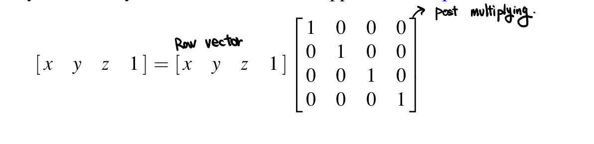
However, some texts use 1x4 matrix(row vector) to represent a point and transform it by multiplying it by a matrix on its right(Postmultipliying). Because the conventions are equivalent, it is immaterial which is used as long as consistency is maintained.
2.1.3 Concatenating transformation: multiplying transformation matrices.
The advantage of representing transformations as square is that they can be multipled together, which concaatenates the transformation and produces a compound transformation. This enables a series of transformations, M_i, to be pre multiplied so that a single compound transform matrix, M. Note that matrix multiplication is associative((AB) C = A(BC)) but not commutative (AB!= BA).
When using the convention of postmultiplying, a point represented by a row vector by the same series of transformations used when premultiplying a column vector.
2.1.4 Basic Transformations
Basic transformations rotate, translate, and scale will be considered. These transformations are affine transformations. The transformation matrices are the same whether space is left- or right-handed. Restricting discussion to the basic transformations allows the fourth element of each point vector to be assignmed the value one and the last row of transformation matrix to be assigned the value [0 0 0 1]

The x, y, z translation values of the transformation are first three values of the fourth column. The upper left 3x3 submatrix represents rotation and scaling. Setting the submatrix to an identity produces this.

A transformation consisting of only uniform scale is represented by the identity matrix with a scale factor S, replacting first three elements along the diagonal. Nonuniform scale allows for independent scale factors to be applied to the x-, y-, and z-coordinates of point and is formed by placing S_x, S_y, S_z.

Uniform scale can also be represented by setting the lowest right most value to 1/S. In the homogeneous representation, the coordinates of the point represented are determined by dividing the first three elements of the vector by the fourth. This technique invalidates the assumption that the lowest rightmost element is not one.

Values to represent rotation are set in the upper left 3x3 submatrix. In a right-handed coordinate system, a positive angle of rotation produces a counterclockwise rotation. In a left-handed system, a positive angle of rotation produces a clockwise rotation.

This is for x-axis rotation, which only x value is maintained.
Combinations of rotations and translations are referred to as rigid transformations because distance is preserved and te spatial extent of the object does not change; only its position and orientation in space are changed. Similarity transformations also allow uniform scale in addition to rotation and translation. These transformations preserve the object's intrinsic properties(dihedral angles : the angle between two planes, both of which pass through same bond) and relative distances. Nonuniform scale however, change the object properties. A shear transformation is a combination of rotation and nonuniform scale and creates columns(rows) that might not be orthogonal to each other. Any combination of rotations, translations, and uniform/nonuniform scales still retains in the last row of three zeros followed by a one. Any affine transformation can be represented by a multiplicative 3x3 rotations followed by an additive three-element vector (translation)

2.1.5 Representing an arbitrary orientation
Rigid transformations(rotations and translations) are very useful for moving objects. These rigid transformations can be represented by a rotation followed by a translation. The rotation transformation represents the object's orientation relative to its definition.
Fixed-angle representation
Orientation is a series of rotations around the principal axes. Consider that an aircraft is defined at the origin of a right-handed coordinate system with its nose pointed down the z-axis and its up vector in positive y-axis direction. Now imagine the object moves to position in world space so that its center is at (20,-10,35)

its nose is oriented toward (3,-4,5); this will be referred to as the aircraft's desired orientation vector. In general, such orientation can be effected by a rotation about the z-axis to tilt the object, followed by a rotation about the x-axis to tip nose up or down, followed by a rotation about the y-axis to swing the plane. This sequence is not unique; others could be constructed as well.
The transformation that takes the aircraft to its desired orientation can be formed by determining the sines and cosines necessary for the x-axis rotation matrices. The length of the orientation vector is sqrt(3^2+(-4)^2+5^2)=sqrt(50). In first considering the x-axis rotation, initially position the orientation vector along the z-axis so that its endpoint is at (0,0, sqrt(50)). The x-axis rotation must rotate the endpoint so that it is -4 in y. By the Pythagorean Rule, the z-coordinate of the endpoint would be sqrt(34).

we have sin(psi)=4/sqrt(50) and cos(psi)=sqrt(34)/sqrt(50). The x-axis rotation matrix looks like this.

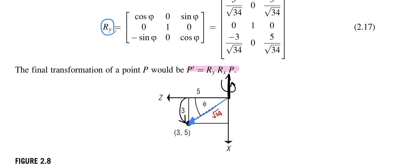
After the pitch rotation, a y-axis rotation is required. The projection in the x-z plane is (3,0,5) with sin(psi)=3/sqrt(34), and cos(psi)=5/sqrt(34). The fianl transformation of a point P would be P' = R_y R_x P.
Matrix of direction cosines is an alternative way to represent a transformation to a desired orientation. Consider transforming a copy of the global coordinate system so that it coincides with a desired orientation defined by a unit coordinate system. Note that the transformation matrix, M, should map a for each unit axis vector into the each axis. These mappings can be assembled into one matrix M.

Since a unit x-vector multiplied by a transformation matrix will replicate the values in the first column of the transformation matrix, the columns of transformation matrix can be filled with the coordinates of the desired transformed coordinate system.
In the example of transforming the aircraft, the desired Z-axis is the desired orientation vector(new Z-axis), w=[3,-4,5]. The desired X-axis can be formed by taking the cross-product of the original y-axis and the desired Z-axis, u=[5,0,-3]. The desired Y-axis can then be formed by taking the corss-product of the desired Z-axis and the desired X-axis, v=[12,34,20].

2.1.6 Extracting transformation from a matrix
For a compound transformation matrix, a set of individual transformations can be extracted from the matrix. Series of transformations to produce compound transformation is not unique. An arbitrary rigid transformation can easily be formed by up to three rotations about the principal axes.
The last row of a 4x4 transformation matrix, if the matrix does not include a perspective transformation, will have zero in the first three entries and one as the fourth entry. The first three elements of the last column represents a translation. The upper left 3x3 submatrix of original one can be decomposed into three rotations around principal axes.

if the matrix includes a uniform scale factor, the rows of the 3x3 submatrix will form orthogonal vectors of uniform length. The length will be the scale factor, which forms the decomposition of the compound transformation. If the rows of the 3x3 sub matrix form orthogonal vectors of unequal length, then the lengths represent nonuniform scale factors that precede any rotations.
2.1.7 Description of transformations in the display pipeline
Transformation of the display pipeline can be explained in terms of concatenating these basic transformations. Note that the descriptions of eye space and the corresponding perspective transformation are not unique. They depend on where the observer is placed along the z-axis to define eye space, whether the eye space coordinate system is left- or right-handed, and the range of visible z-values in image space.
Object space to world space transformation
Trnasformation of an object from its object space into world space is a series of rotations, translaations, and scales that are specified by the user to place a transformed copy of the object into a world space data structure. In some systems, the user is required to specify this transformation in terms of a predefined order of basic transformations. In either case, the series of transformations can be compounded into a single object space to world space transformation matrix.
World space to eye space transformation
A rigid transformation is performed in preparation for the perspective transformation. The transformation is designed so that, in eye space, the observer is positioned at the origin, the view vector alighns with the positive z-axis in left-handed space, and. The up vector aligns with the positive y-axis the transformation is formed as a series of basic transformations. First, the observer is moved to the origin. Then the observer's coordinate system(view, up, and thrid) is transformed by up to three rotations so as to align the view vector with the global negative z-axis and the up vector with the global y-axis. The z-axis is flipped by negating the z-coordinate. All of these transformations can be produced as a single compound world space to eye space transformation matrix.
Perspective matrix multiply
The perspective matrix multiplication is the first part of the perspective transformation. Computation performed by the perspective transformation is dividing the x- and y-coordinates by their z-coordinate and normalizing the visible range in x and y to [-1,1]. This is accomplished by using a homogeneous representation of a point, producing a representation in which the fourth element is Z_e tan(psi). Z_e is the point's z-coordinate in eye space and psi is the half angle of view in the vertical or horizontal direction. The z-coordinate is transformed so that planarity is presesrved and the visible range in z is ampped into [0,1].
Perspective Divide
Each point has a nonunitary fourth component that represents the perspective divide by z. Dividing each point by its fourth component completes the perspective transformation. Clipping procedure operates on homogeneous representation of points is a separate step before the perspective divide.
Clipping, the process of removing data that are out side the view frustrum, can be implemented in a variety of ways.
It is important to perform clipping in z using the near clipping distance before perspective divide to prevent divide by zero and to avoid projecting objects behind the observer.
Image to screen space mapping
The result of the perspective transformation maps visible elements into the range of [-1,1] in x and y. This range is mapped into the user-specified viewing area of the screen-based pixel coordinate system.
'ComputerGraphics' 카테고리의 다른 글
| Orientation representation (0) | 2022.10.26 |
|---|---|
| Error consideration (0) | 2022.10.24 |
| Spaces and transformations (0) | 2022.10.18 |
| Spaces and transformations (0) | 2022.10.18 |
| Digital Video/Audio (0) | 2022.10.17 |


댓글